Blended Wing Body
1 Objective
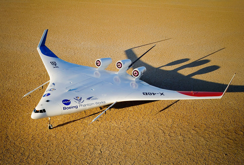
The objective of this project is to analyze the aerodynamic properties of a Boeing-designed Blended Wing Body (BWB) aircraft, and to redesign the BWB geometry in order to improve static stability at cruise while minimizing the impact on drag.
2 Baseline geometry
The baseline geometry definition is provided in an AVL input file with associated airfoil data files in an archive on the Stellar 16.100 site. AVL is a vortex lattice code written by Prof. Mark Drela and Dr. Harold Youngren. A link to the AVL website is provided on the 16.100 Stellar site.
3 Operating conditions and design constraints
3.1 Cruise requirements
1. Cruise altitude is 35,000 feet
2. Mach number M∞ = 0.8
3. Assume cruise weight is maximum take-off weight (MTOW) and that MTOW = 800,000 lbs.
4. A minimum of a 5% static stability margin. You may assume that center of gravity of the aircraft can be placed at the center of pressure by appropriately distributing the fuel throughout flight.
5. Flaperons are not to be deflected in cruise.
3.2 Approach & stall requirements
1. Approach speed = 150 knots (set by air traffic safety)
2. If the sectional clmax < 1.2, then slats will not be needed in the design. With slats, then clmax = 1.6. Note: these limits will set the maximum lift and, therefore, determine the stall speed.
3. Approach speed = 1.3 × stall speed (for safety)
4. Aircraft is carrying full payload with 25% fuel remaining. Assume aircraft empty weight is 400,000 lbs, payload is 200,000 lbs, and fuel weight is 200,000 lbs.
5. A minimum of a 5% static stability margin at approach and stall speeds. You may assume that center of gravity of the aircraft can be placed at the center of pressure by appropriately distributing the fuel throughout flight.
6. Flaperons can be deflected in approach and stall conditions, but the same flaperon deflections must be used for both.
3.3 Geometric design constraints
To meet the operating condition requirements, a wide range of geometry modifications can be pursued. However, a few geometric design constraints must be met by the redesigned BWB. Specifically:
1. The number of flaperons can be decreased and the location and size of the flaperons can be changed. However, the size of the flaperons should be less than the minimum of either 15 feet or 30% of the local chord.
2. The wing span can be not be increased beyond the current length of 280 feet.
3. Tails are not allowed (i.e., the plane must still be a blended-wing body).
4. Any geometry modification must result in a smooth geometry at the design condition. For example, if the airfoil sections are redesigned, the airfoils must not have discontinuous slope changes. Also, the spanwise distribution of the chord, sweep angle, geometric twist, etc., must be smooth (no sudden changes).
5. The size (chord and maximum thickness) of the center of the BWB, specifically the first 50 feet from the wing root, cannot be modified. This is to ensure that the passenger compartment does not change size.
4 Analysis methodologies
Vortex lattice (and AVL in particular) is recommended as the basis for approach and stall analysis, where compressibility effects should be minimal. You will need to include some kind of correction for friction drag and pressure drag. This could be done using AVL’s parabolic profile drag model, with input from XFOIL. Other methods for drag correction are certainly possible. At the cruise condition, wave drag will become important, and in principle one should consider computational options other than AVL. This may be challenging if you don’t have a CFD code at your fingertips, so if you use AVL for cruise, you should attempt to estimate the wave drag in some manner—in addition to accounting for friction and pressure drag
5 Report outline
Note: in all analyses, use the original reference areas and lengths for non-dimensionalization. In other words, for the reference area, use Sref = 7840 sq. ft. and for the reference length use cref = cmac = 30.75 ft.
5.1 Wind tunnel comparison: nominal geometry
Wind tunnel data is available for a 1/47 scale model of the BWB. The wind tunnel tests were performed in the Wright Brothers Wind Tunnel at velocities of 50 and 100 miles per hour. First, correct this data to account for the impact of the tunnel walls and the mounting mechanism. Then, compare the resulting aerodynamic characteristics to those predicted by your analysis methodologies. This comparison will be performed at the freestream conditions (i.e., Mach and Reynolds numbers) of the Wright Brothers Wind Tunnel, rather than at cruise, approach, or stall conditions. Additional details on the wind tunnel data will be posted on the Stellar website. The requirements for the comparison are to:
• Describe corrections made to account for the tunnel walls and the model mount (specifically the cylindrical mount, the pitch adjustment rod, and the flat plate sting).
• Compare CL versus angle of attack for your analysis and the wind tunnel.
• Compare CL versus CD for your analysis and the wind tunnel.
• Compare the pitching moment coefficient about the aerodynamic center, CMac versus CL. Note, in this plot, fix the location of the aerodynamic center as the aerodynamic center of the BWB at zero lift as estimated by your analysis. 5.2 Cruise analysis: nominal geometry For the original BWB:
• Estimate and compare the drag and the lift-to-drag ratio.
• Estimate xac/cmac, xcp/cmac, and the stability margin.
• Plot cl(y), cl(y)c(y)/cmac, and the induced angle of attack. Or, alternatively, include a plot of the pressure distribution on the upper and lower surface and at several airfoil cross-sections along the span.
5.3 Approach & stall analyses: nominal geometry
For the original BWB:
• For approach and stall conditions, estimate xac, xcp, and the static margin.
• Plot cl(y), cl(y)c(y)/cmac, and the induced angle of attack at the approach conditions.
• Plot cl(y), cl(y)c(y)/cmac, and the induced angle of attack at the stall conditions. Also include a zoomed in version of this plot which highlights the cl range around the clmax constraint. For example, if you are using slats, zoom in the plot from approximately, 1.4 < cl < 1.8.
5.4 Redesign strategy
Briefly describe the redesign strategy that you pursued. Provide an aerodynamic justification for why you have chosen this strategy.
5.5 Redesigned BWB geometry
• Describe the final modifications made to the geometry including a comparison of the geometry parameters that changed from the original to the redesigned BWB. When appropriate, plots should be made to demonstrate these changes.
• Tabulate the location and size of the flaperons for the original and redesigned BWB. Also, include the deflection angles of the flaperons at the approach condition for the original and redesigned BWB.
• An AVL input file for the redesigned BWB must be uploaded to the 16.100 Stellar website. If you modified the airfoil sections, input files for the modified airfoils should be uploaded as well (in a zip archive).
5.6 Approach, stall, and cruise analyses: redesigned geometry
Repeat the aerodynamic analysis you performed for the nominal geometry, at approach, stall, and cruise conditions, for your redesigned geometry. In other words, repeat Sections 5.2 and 5.3 for the redesigned geometry.
5.7 Review of proposed design strategy
If your proposed design strategy worked, you do not need to do anything for this section. If your design strategy did not work, you must explain why your initial reasoning proved to be incorrect. Furthermore, you should propose an alternative design strategery and provide aerodynamic justifi- cation for this alternative strategery. Note: you are not required nor in any way expected to implement this alternative strategery.
6 Other report requirements
6.1 Cover page
A cover page must be included listing the team members. All team members must sign the cover page of the report indicating that the report is the result of their work and that the work breakdown is correct.
6.2 Work breakdown
Include a detailed breakdown of how the work was split among team members, including the amount of time spent by each team member working on the project. Include the time spent in class or lab sections.
6.3 Bibliography
Include a bibliography for any references you utilized, including online resources.
6.4 Formatting conventions
• Only one report should be submitted by each team.
• The report should be typeset and submitted electronically on the 16.100 Stellar website by 4 pm on Wednesday 10 December 2014.
• Report has the following formatting limitations:
– no more than 5.5 lines per inch of text.
– no more than approximately 15 characters per inch. Captions and annotations on figures, tables, etc. can have more than 15 characters per inch but must be legible.
– 1 inch page margins on all sides using 8.5 inch by 11 inch paper.
– no more than 20 pages including everything (all figures, tables, equations, etc.) except for the cover page, work breakdown, and bibliography.
– no more than 2 pages for the work breakdown.
– no page limit on the bibliography